Wednesday, December 7, 2016
11/30-12/7
In the last week we have worked on the last presentation and final report. I spent a few hours on the final report working on the abstract, executive summary, and other parts. I did research on previous final reports. I also coordinated with my group to make sure we have everything ready to present to Eric. Eric asked for our 3D model of our new brackets and a CAD image of the bogie making the clearances necessary. I mentioned to the group that we should a little bit more to show, just to help give an idea to show our direction.
Blog #14
Hi,
This week our team worked on presentations and the first draft of the final report. We finally received the PLA filament and will begin printing the brackets as soon as possible. We also fixed a few tiny details and placed four bogies on the track to show clearances. Afterward, we did a FEA on the ALU-6061 corner bends and the PLA U-Brackets. We researched PLA to determine effectiveness of infill percentages as recommended by Michael Kemp. This week, we will be presenting and afterward, we will be talking to Eric, Furman, and Ron about what we have done thus far. We will also be submitting our individual evaluations this week.


Wednesday, November 30, 2016
Blog #13 11/30/2016
Hi,
This week we got our Bill of Materials approved by Eric and have ordered the PLA filament from Amazon for under $100. The filament should arrive today and be sufficient for 30 castings of our U-bracket which Jezreel has volunteered to 3D print for us with his printer throughout winter break. We will be printing them at 70% ink-fill (heeding Michael Kemp’s advice, who suggested 70% is approximately the same as 100% ink-fill). After we print the first one, we will be comparing it with the previously printed 100% ink-filled one to see differences. Since it was Thanksgiving weekend, we did not burden ourselves with too many tasks. However, we were working on presentation #3 and starting our final report. For the first draft of our final report that is due this Friday 12/2/2016, we will be working on it throughout this week so that we have less to do for the final draft of the final report. For the coming weeks, we will be working on the final report and planning for the beginning of next semester.
Tuesday, November 22, 2016
11/23/2016 Blog #12
Hi,
this week, we created a Bill of Materials which we e-mailed to three people: Eric Hagstrom, Michael Kemp, and Neil Shankar; they are responsible for approving our budget. Jezreel went ahead and found the PLA filament on Amazon which was the item needed for our Bill of Materials. We also dimensioned the overall dimensions of the track to make sure it fit the given area when presenting at Paseo Prototyping and Maker's Faire which is within a 15 by 15 feet area, which it does. It also allows other teams to know approximately how large the track is (13 by 13 feet). On Friday, Jez and I went to see VanderBend to obtain answers. Having gone to VanderBend, we saw the many things they were able to accomplish so that our minds were unshackled from only the experiences we have had with countering the problems we've encountered.
this week, we created a Bill of Materials which we e-mailed to three people: Eric Hagstrom, Michael Kemp, and Neil Shankar; they are responsible for approving our budget. Jezreel went ahead and found the PLA filament on Amazon which was the item needed for our Bill of Materials. We also dimensioned the overall dimensions of the track to make sure it fit the given area when presenting at Paseo Prototyping and Maker's Faire which is within a 15 by 15 feet area, which it does. It also allows other teams to know approximately how large the track is (13 by 13 feet). On Friday, Jez and I went to see VanderBend to obtain answers. Having gone to VanderBend, we saw the many things they were able to accomplish so that our minds were unshackled from only the experiences we have had with countering the problems we've encountered.
Wednesday, November 16, 2016
11/16/16
Hi,
This week we maintained contact with Kearny Foundry and realized the price was too expensive ($1400 for mold and 30 castings), especially since they will not be able to machine the press fit or holes either. It would be more expensive to let another company finish off the machining that we needed done, but if we simply 3D printed, it would solve the problems of needing to ask two companies for help and it would save tons of money. The process would take about half of the time (two to three weeks instead of four) and would eliminate the need to find a machining company or create a repeatable drilling process. We have also been trying to organize a visit to Vanderbend Manufacturing for our group and several others to get quotes, contacts, and answers. Vanderbend has been communicative. They have seen our designs and give us some feedback. We are still waiting to hear back from them on a quote.
This week, our goal is to start the final report and complete a bill of materials for all of the things we need to 3D print. Fortunately, one member of our team (Jezreel) has a 3D printer, so we would be able to print it in the weeks of winter break.
Wednesday, November 9, 2016
Blog #10 11/9/2016
Hi,
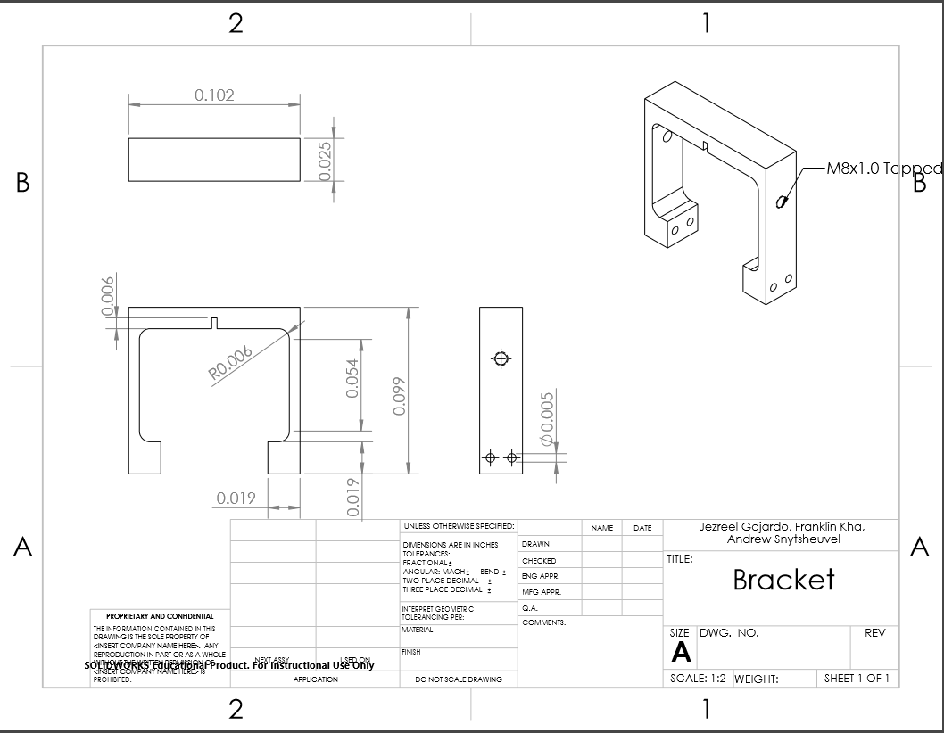
This week we focused on turning all of the SolidWork parts into drawings and pdfs to obtain quotes from Kearny Foundry and Vander-Bend; there were a lot of parts to draw; below is two example pictures of fifteen. We needed to hurry all of the drawings because after getting a quote from the two companies next week, we need to put it in our Bill of Materials before submitting it to our treasurer. We have also been maintaining contact with the track manufacturing team who have been working diligently to create a tool to bend the material so that we could reduce the cost and finish the products at our own disposal. Moreover, we have been arranging for a meeting with Vander-Bend in person with several other members of the Spartan Superway Project.

Wednesday, November 2, 2016
Blog #9 11/2/16
Last week we presented again on the status of our project. We believe the presentation went well and announced that we are looking into beginning manufacturing. At this time, we have a running dialogue with Kearny Foundry about casting some newly designed brackets. At this time they have asked for a few more details from us before they can give us a quote. They also informed us that any final machine work would have to be done elsewhere.
We are also trying to get some work done at Vanderbend. At this time, we are coordinating with the Fabrication Team, and Full Scale Team to get a time to meet with the staff of Vanderbend. We have also been informed there is another senior project in the Industrial Studies department that would like to meet with Vanderbend for production.
We are creating a bill of materials to get our budget approved. It is still a work in progress to get in contact with manufacturers. Below you can see what we know so far. This will be further refined prior to submission.

Tuesday, October 25, 2016
Blog #8 10/26/2016
Hi,
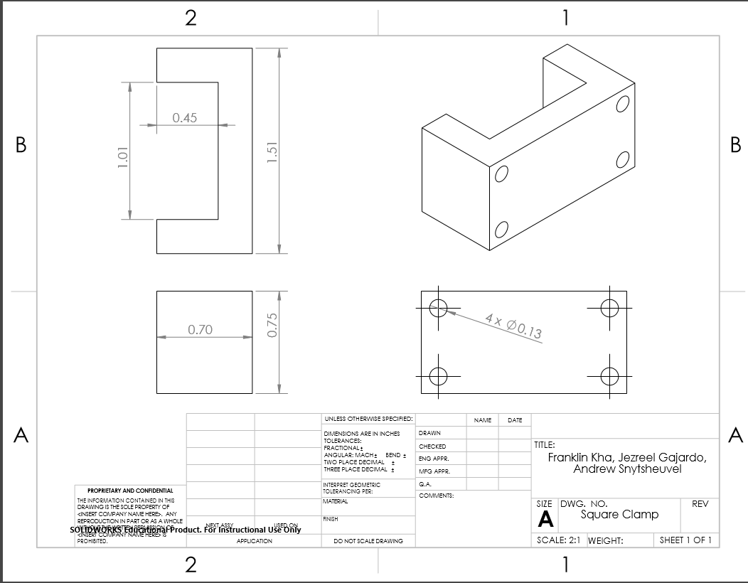
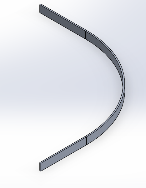
This week our team was busy redesigning the brackets in accordance with what was asked of us after the individual group meeting with Furman and Eric. We also spent a deal of time working on the PowerPoint presentation, tabulating inventory , and drafting drawings to e-mail companies. We have started a Bill of Materials (Image 2) and should have that completed before November 15th (the deadline). We have yet to contact Vander Bend because we are fixing the rest of our track before we send them the improved curvatures. Despite not yet asking for a quote, we have reached out to them and obtained several contacts so we will keep in touch with them as soon as we are ready. We have e-mailed Kearny Foundry for a quote on how much it would cost to create a mold of our bracket (Image 1) and the cost of each filling of ALU 6061.
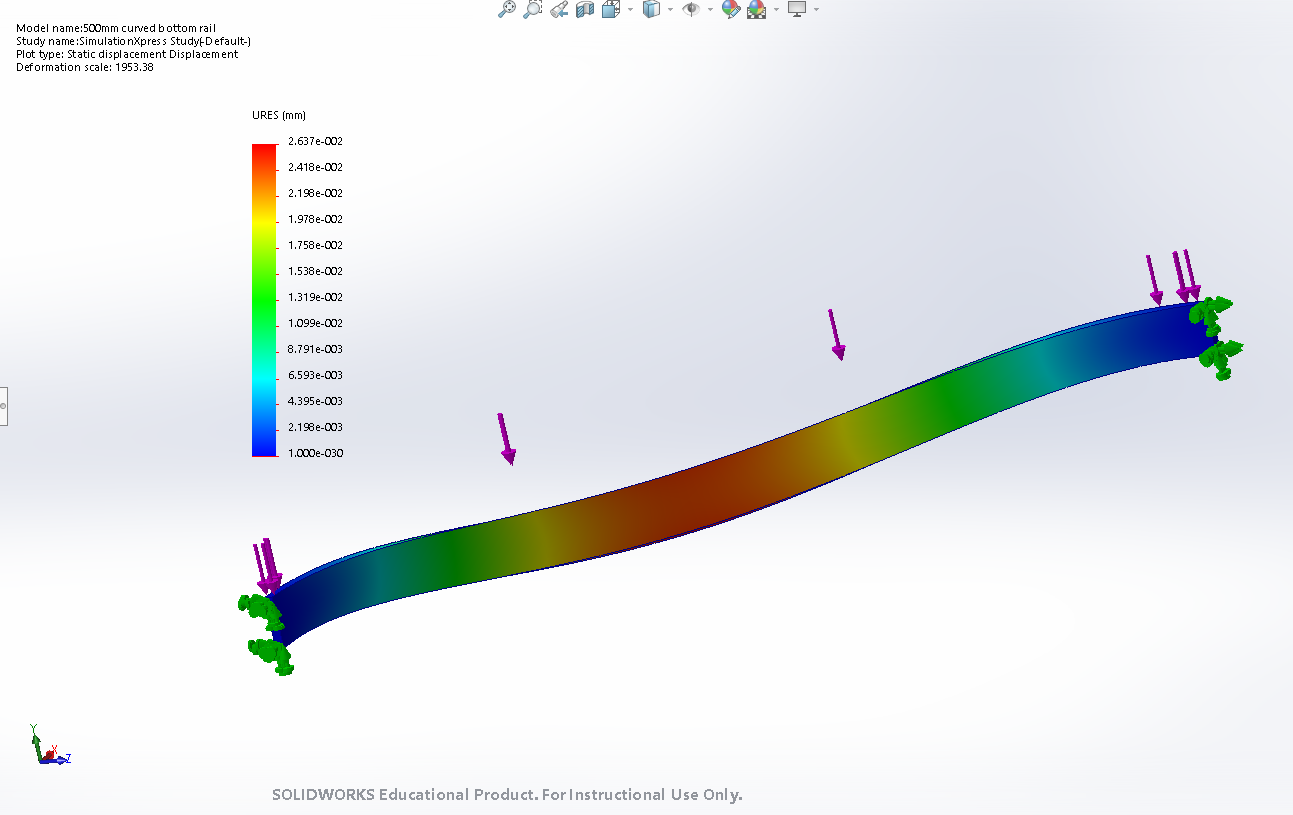
One of the problems we confronted this week included being unable to perform Finite Element Analysis (FEA) on an assembly and thus, we had to redraw the track as a single part. We simply redrew the loop to FEA (Image 3), where we accounted for the rest of the track with fixed points and proper weights. And below are several pictures of, but not all, the things we accomplished this week as we will be updating these into the overall Spartan Superway Folder for the others to access.


Wednesday, October 19, 2016
Blog #7 10/12-10/18
Hi,
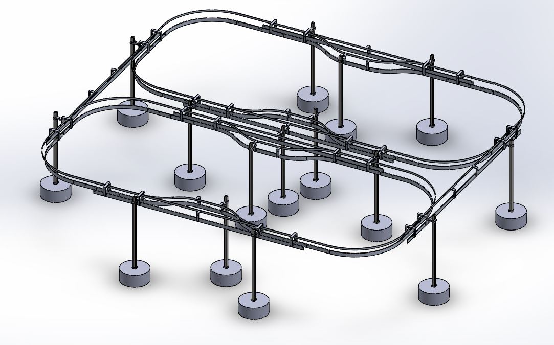
This week our team attended the seminar about the ME195 Report hosted by Dr. Agarwal. We also continued our improvements of the track which are shown below in Figure 1. Figure 2 shows how the U-bracket is connected to the support post. We quickly resolved our little problem with converting the metric system to english units. We attempted some finite element analysis (FEA) but it was limited to single pieces and the program could not do a finite element analysis of the entire assembly and so we will try again tomorrow with the full solidworks edition at the engineering building. We were able to do Finite element analysis on the U-bracket shown in Figure 3. Figure 3 shows the displacement of the bracket when a 5lbf acts on the part. The orange arrows shows where the force is applied. The green arrows simulate how it would be mounted. Reference back to Figure 2 for how it is mounted. As we can see, the left side goes under compression which would cause the track to droop downwards and not keep the track uniform. This week we will finish the FEA, presentation PowerPoint, update Gantt Chart, and start working on our bill of materials.
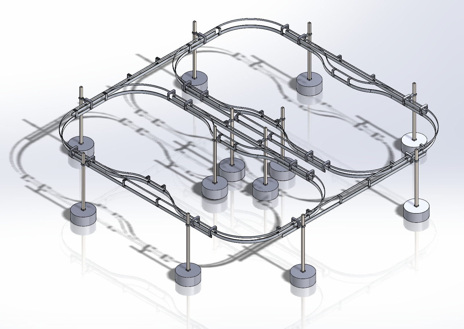
Figure 1: Full track assembly

Figure 2: U-Bracket mounted to Support Post
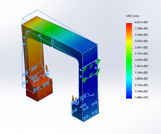
Figure 3: FEA on U-bracket
Wednesday, October 12, 2016
Blog #6 10/5-10/11
In this past week, we presented our project to the class and instructors. Prior to the presentation there was a big push that all the teams show that they had completed around 50 hours of work since the start of the project. We realized we have not worked for that many hours however we believe we are on track to complete our goals for the semester and the year. By this point we should have run finite-element analysis so we could get a jump on building the rapid prototype. We will be doing that in the coming days and spend the next week pushing to get some parts manufactured using the materials and tools in the design center.
At the end of our presentation, Professor Furman asked us some questions that we were prepared to answer, but we would like to provide more details about our plans. One of the things he mentioned was that the screws that hold up the brackets are problematic. This is very true, the screws are very tiny and are either stripping or bending. Ideally we would like to actually weld the brackets to the rail where we can without making assembly/disassembly more complicated. The brackets on each part (A-F) would be welded using the TIG welder, and where each part mates together, would be bolted together. Any remaining brackets and connections would have to use all new bolts and screws.

At the end of our presentation, Professor Furman asked us some questions that we were prepared to answer, but we would like to provide more details about our plans. One of the things he mentioned was that the screws that hold up the brackets are problematic. This is very true, the screws are very tiny and are either stripping or bending. Ideally we would like to actually weld the brackets to the rail where we can without making assembly/disassembly more complicated. The brackets on each part (A-F) would be welded using the TIG welder, and where each part mates together, would be bolted together. Any remaining brackets and connections would have to use all new bolts and screws.

Another issue Furman had mentioned is that bending sections A-D could be difficult to do according to our design (2 straight sections with a bend in the middle). This was something that came up several weeks ago as we discussed our designs with the fabrication team. Ultimately, both of us decided to make a serious attempt at manufacturing the parts the more difficult way because it should make assembly the track more precise. We have a few ideas on how it can be manufactured but are aware that we may have to refer back to the previous design method.
Wednesday, October 5, 2016
Blog #5 10/5/2016
Hi,
At the beginning of our class we met with the other 12th scale groups to discuss any changes and expectations. Upon agreement, it appears that none of the work we are doing so far will collide with each other at the moment. This week, we continued working on our presentation because we wanted to accurately represent the amount of work we have done. We updated our Gantt chart because we needed to actually finish designing a bit sooner than expected. Our team has been gradually outputting more designs each week as displayed below. This coming week, we will be presenting and the plan is to finish designing, completing calculations, and running FEA for the designs by the 19th of October.
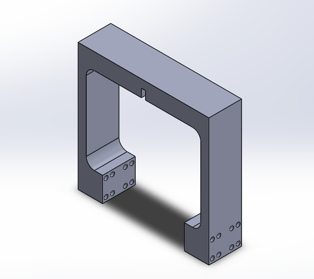
Figure 1. Update on bracket. This should keep the track width uniform.

Figure 2: Overall dimension of bracket.
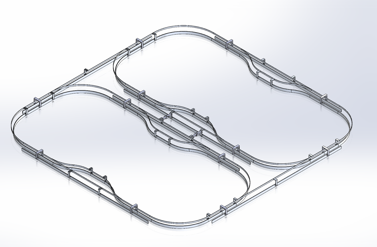
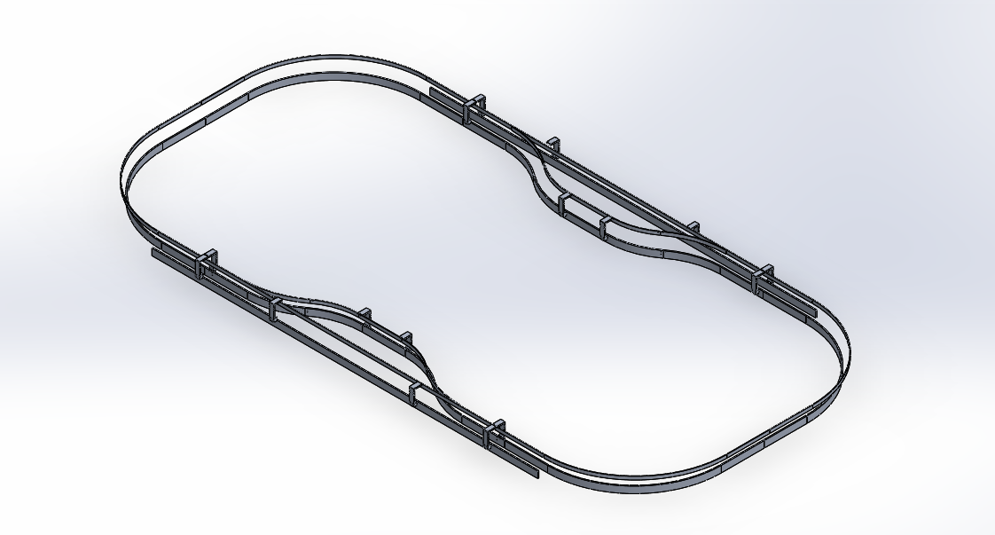
Figure 3: Two Loop Track
Tuesday, September 27, 2016
Blog #4 9/21-9/27
Hi,
This week our team once again met up with the other groups at the beginning of class to ensure we are all on the right path without hindering other groups’ progress. We mentioned how our plan was to completely redesign the track, but the other teams may continue to use the current loops to test their products since the redesign dimensions will not be too different. Afterward, we documented the dimensions and then proceeded to talk about the following week’s plans. Firstly, the presentation was of utmost importance since it was the soonest. We drafted a brief presentation and agreed to meet up again on Saturday to further improve it, which we did. And after the presentation, we plan on starting to stay at campus to start designing on the Solidworks programs on the second or third floor of Engineering building. We have already mentioned this to the other groups that we will be returning to campus after meeting up with everybody for our weekly meetings. However, they will still be able to reach us via Slack (a group chat application) fairly easily and we will be a text message away. Our team has also drafted a few basic designs for what we plan on doing with the mounts and loops for the track. We will be more thorough with the coming weeks, but the pictures are displayed below and the files will be made available to other groups in the 12th scale. Overall, the communication has been pretty good and the 12th scale seem to have a pretty strong foundation.

Track Improvement Team
Wednesday, September 21, 2016
Initial Track Design and Overview of Previous Week
This week our team noticed that there was a terrible communication issue because there were overlapping tasks and the teams have yet to confront each other. Thus, everybody (from the 1/12th scale) gathered to hold a meeting on how to maintain better communication and future plans. We all agreed that we will be holding weekly meetings at the beginning of each session and that all files will be shared in the 1/12th scale google drive that was set up. This way, it allows people to access the files they need at any time and it will be saved for future years. We also joined an app called ‘Slack’ which allows us to group chat more easily if we needed to ask something urgent since most of us do not instantly reply to Emails (which is different for our phones). After the meeting, our individual track improvement team talked about our plans for the coming weeks. The Gantt chart will need an update after confirmation this following week, but it appears that next week, we will be documenting measurements of the entire track due to the lack of documents and measurements found in the previous reports. And for the coming weeks after a long discussion we decided we will be redesigning the entire track so that we can create a workable design by the end of the semester. As for the other teams, they can use the working loop to test their equipment and addition. Our changes to the new track will not be absurdly different but the measurements will be more precise and smooth, hopefully. As of now, our blogs have been rather short due to the need to establish a proper foundation, but I believe that slowly our blogs will get more extensive and detailed.
The following figures show what we plan to do for improvements of the track. We will look into changing the design of the bracket since the previous brackets lacked structural support and caused the guide way to slack at key parts of the track which is shown in figure 1. Figure 2 shows that the previous track design has some flaws in terms of making the track easier to manufacture, at least we think it would be easier. Figure 3 shows how we plan to go about this. Points A, B, C, and D will all be the same curvatures. Points F and E will also be the same. We are aiming to basically have two parts built. Figure 4 shows how we plan to attach each loop together since we would want more than one loop.


The following figures show what we plan to do for improvements of the track. We will look into changing the design of the bracket since the previous brackets lacked structural support and caused the guide way to slack at key parts of the track which is shown in figure 1. Figure 2 shows that the previous track design has some flaws in terms of making the track easier to manufacture, at least we think it would be easier. Figure 3 shows how we plan to go about this. Points A, B, C, and D will all be the same curvatures. Points F and E will also be the same. We are aiming to basically have two parts built. Figure 4 shows how we plan to attach each loop together since we would want more than one loop.

Figure 1

Figure 2

Figure 3
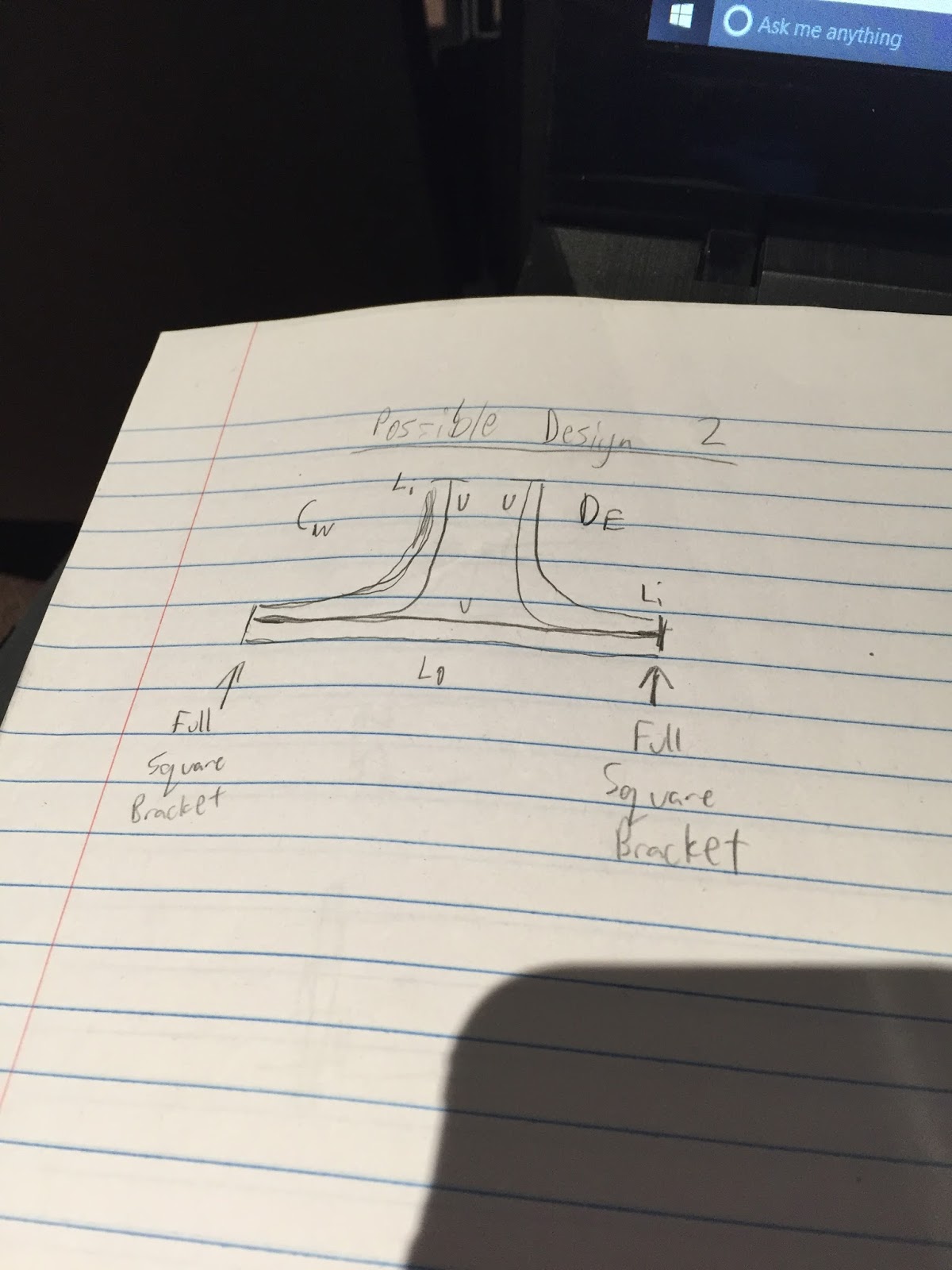
Figure 4
Wednesday, September 14, 2016
Track Improvement Update
This week, our team agreed to simply expand on tentative ideas for improving the current track given to us. We spoke with other teams about the bogie and they said that the contact points for the bogie to the track will be the same so that we know there will be no changes needed to the track with respect to bogie. We also agreed with solar team and bogie team that the track will not dip down because we need to focus on creating a working model before making it more complicated. Looking at the current track, the bends are off such that the bogie cannot follow the track autonomously, if at all. There are also different elevations from the floor that were not accounted for so the tracks are not leveled. Some parts of the guide way are more narrow while some are quite wide. Moreover, the curvatures for the track are weak and weakening since the piece relies on a single bolt on both ends. Lastly, the track is not repeatable because some of the stations are on the outside of the track making it asymmetrical. Below is our updated gantt chart with updated deadlines for Maker Fair and Paseo Prototyping.

Wednesday, September 7, 2016
Track Improvement, Assignment #1
Andrew "AJ" Snytsheuvel, I have solid communication skills, I am also familiar welding, but have not had a lot of practice. ph# 949-285-2498 email: asnytsheuvel@yahoo.com
Jezreel "Jez" Gajardo, I have experience with using solidworks, have used 3D Printers and Laser cutters, decent communication skills. ph# 408-316-9874 email: jezgajardo@gmail.com
Franklin Kha, I have experience with physical assembly of items and pretty good communication/teamwork skills. I have basic knowledge in solidworks and CREO.
ph# (510)857-3222. email: hotnova270@gmail.com
Budget: $5000
Team Responsibilities:The following responsibilities are tentative.
Franklin will be helping mostly with making sure the group is organized and working on reports and assignments in a timely fashion.
Jez is our expert with Solidworks will be are go to on producing CAD drawings and designs.
AJ will be mostly involved with the manufacturing and construction of the track.
Proposed Improvements:

Gantt Chart

Jezreel "Jez" Gajardo, I have experience with using solidworks, have used 3D Printers and Laser cutters, decent communication skills. ph# 408-316-9874 email: jezgajardo@gmail.com
Franklin Kha, I have experience with physical assembly of items and pretty good communication/teamwork skills. I have basic knowledge in solidworks and CREO.
ph# (510)857-3222. email: hotnova270@gmail.com
Budget: $5000
Team Responsibilities:The following responsibilities are tentative.
Franklin will be helping mostly with making sure the group is organized and working on reports and assignments in a timely fashion.
Jez is our expert with Solidworks will be are go to on producing CAD drawings and designs.
AJ will be mostly involved with the manufacturing and construction of the track.
Proposed Improvements:
We think we would like to improve the track to make it even more modular. The concept would be to allow each small loop to be manufactured independently, then be able to piece all the loops together to build larger track, similar to Legos.

Gantt Chart
Subscribe to:
Posts (Atom)